When using this instrument, please do not look directly at the optical interface or the end of the optical fiber with your eyes, avoid eye damage! Any change or modification not explicitly permitted in this manual will deprive you of the right to operate the equipment. To reduce the risk of fire or electric shock, do not expose the equipment to thunderstorm or humid environment. In order to prevent electric shock, do not open the shell, it must be repaired by the qualified personnel designated by the manufacturer.
Battery: The battery in the machine is a special lithium-ion polymer battery. The charging voltage is 5V, and the charging temperature ranges from -5℃~40℃. When the ambient temperature is too high, the charging will automatically terminate. The instrument battery should be charged every one month to avoid battery failure due to self-discharge after long time storage. The temperature range of the battery during long-term storage is -20℃~45℃.
Please use the special AC adapter attached to this instrument and use the external power supply strictly according to the specifications, otherwise the equipment may be damaged.
Fiber End Face Cleaning: Before testing, clean the end face of the tested optical fiber joint with alcohol cotton.
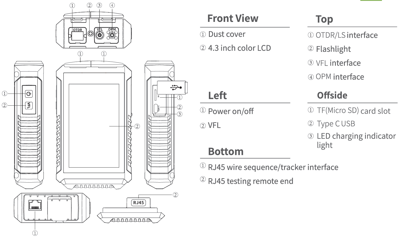
LCD screen: The display of this series of instruments is 4.3 inch color LCD. In order to maintain good viewing effect, please keep the LCD screen clean and clean. When cleaning, the LCD screen can be cleaned by wiping with soft fabric.
The whole machine is guaranteed for 18 months. The battery, charging adapter and optical interface consumables are guaranteed for 6 months. The warranty date shall be postponed one month from the date of manufacture.
Due to the need of design improvement, the contents are subject to change without notice.
Brief
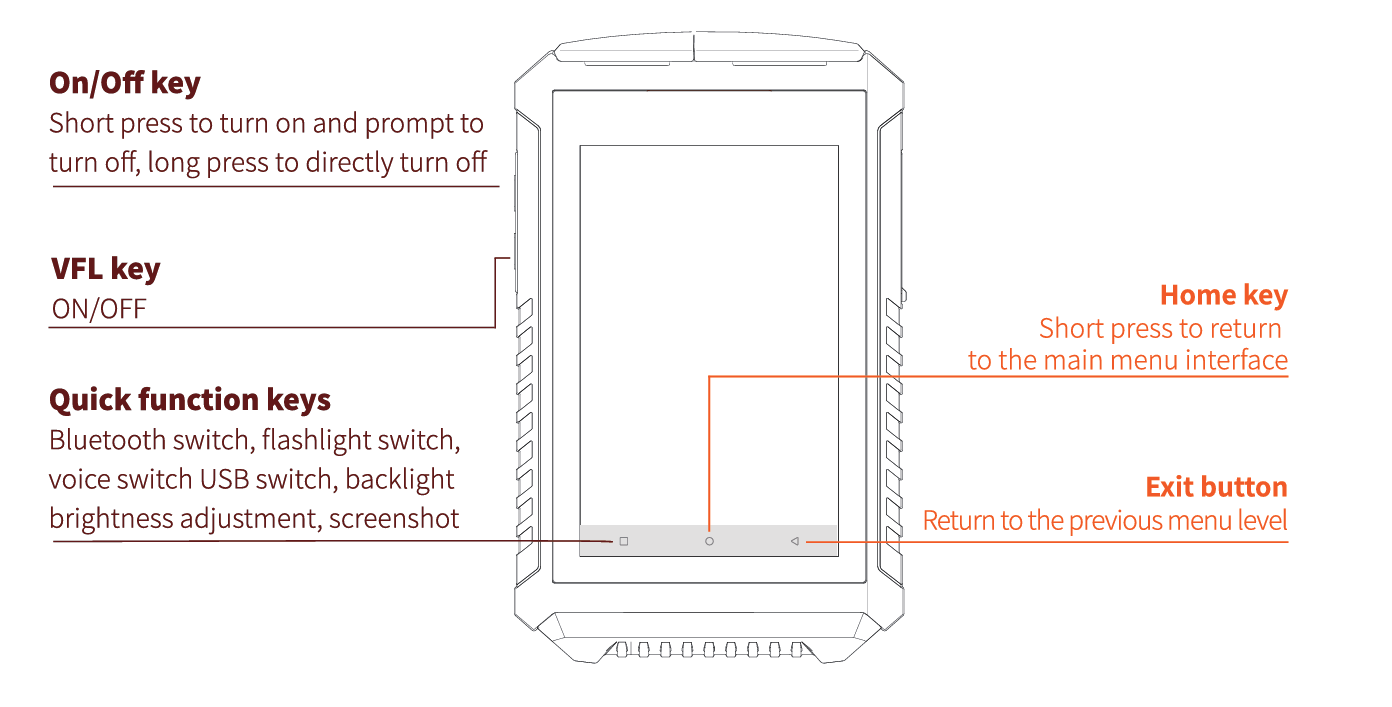
Functional Keys
Main Interface
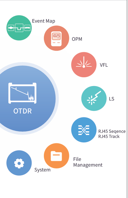
Enter the main menu after power on, there are 8 function modules. Press the function icon to enter the corresponding function interface.
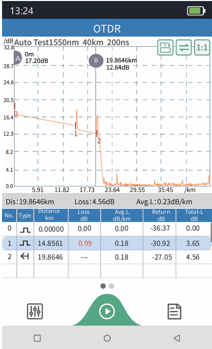
OTDR-Curve
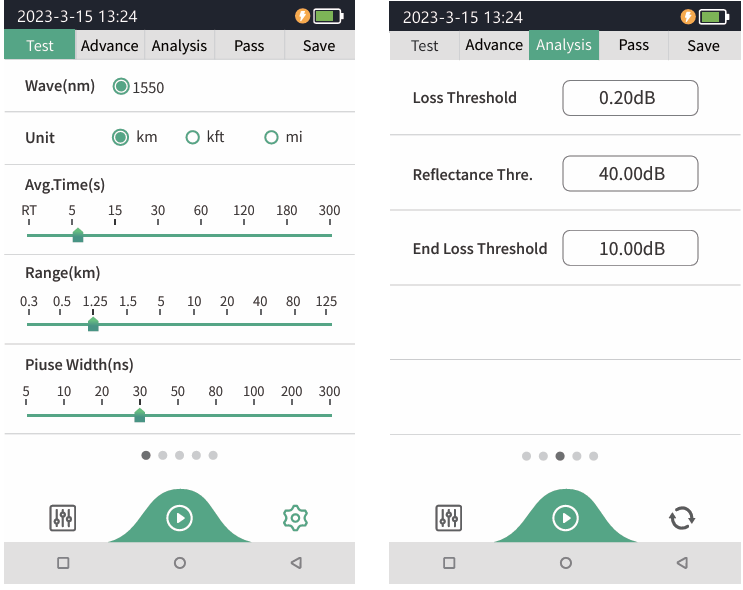
Setting parameters: Select the test wavelength, range, pulse width and time
Mode switching: Real time test, average test and auto test mode switching
Wavelength: Select the test wavelength of OTDR
Test range: Usually required to be set about twice the length of the measured optical fiber
Test pulse width: 5ns~10000ns optional, different measuring ranges, different pulse widths are available
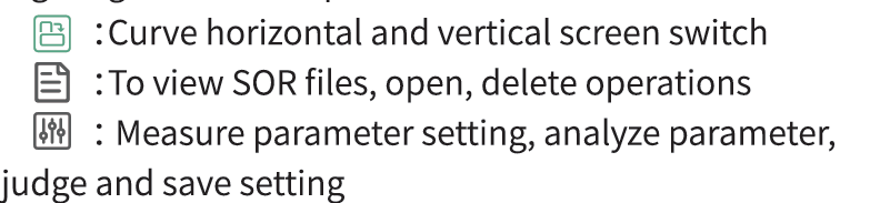 Curve Operation
Curve Zoom, drag: Touch screen gesture operation
Restore initial curve: Double click the screen
Move Cursor: Drag A or B
Curve Operation
Curve Zoom, drag: Touch screen gesture operation
Restore initial curve: Double click the screen
Move Cursor: Drag A or B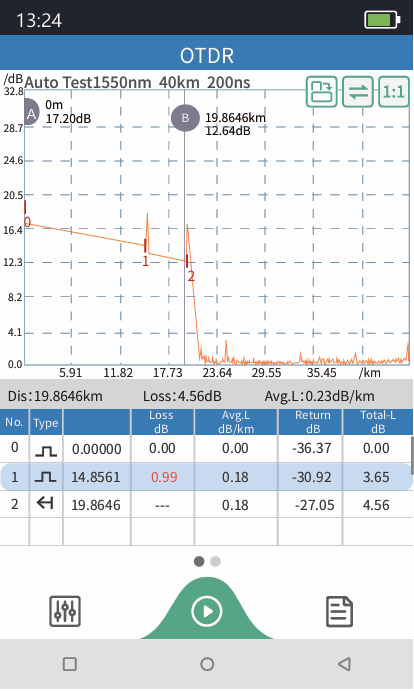
OTDR List
List: the tested results are displayed in the form of a list.
Distance: the distance between AB cursors
Loss: loss between AB cursors
Slope: average loss between AB cursors
In the event list:
NO.: the order of the current event.
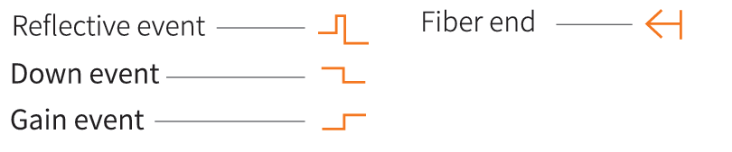
Type: the type of the current event.
Distance: the location of the current event.
Loss: the loss of the current event.
Slope: the loss from the starting point to the current event.
Reflection: the return loss of the current event.
Total loss: the loss from the starting point to the current event.
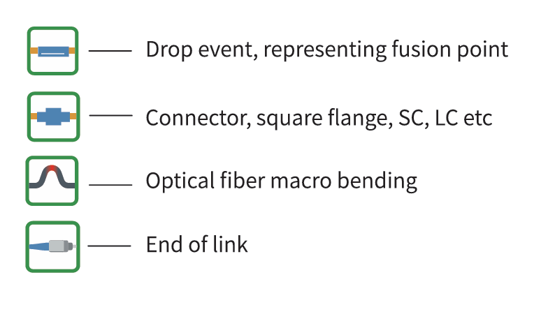
There are five types of events:
Set the refractive index of the test wavelength, select the test unit and sampling mode
The test units are kilometers km, miles mi, thousand feet kft
Sampling mode: Regular, fast and high-precision mode, where high-precision mode takes longer but the test is more accurate.
Event loss threshold: Set the loss threshold of the connection point, weld point, or macro bend in the link that can be tested. The value ranges from 0.1dB to 9.99dB. The default value is 0.2dB. Events greater than the set threshold are listed in the event table, and those less than the threshold are ignored.
Reflection threshold: set the return loss threshold of the link reflection events that can be tested, ranging from -99.99dB~-1dB, and -40dB by default.
End threshold: set end loss at the end of the link that can be tested, ranging from 1dB~99.99dB, 10dB by default.
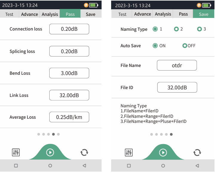
Set the judgment value for the average loss of connection/fusion/bending/link. If it is less than the value, it is judged as "PASS", otherwise it is "FAIL"
Connection loss: This parameter is used to set the threshold for determining the connection loss. If the threshold is higher, the connection loss is considered to be too large.
Fusion loss: Set the threshold for determining the loss of the fusion point. If the threshold is higher, the loss of the fusion point is considered to be too large.
Bending loss: This parameter is used to set the threshold for determining the bending loss. If the threshold is higher, the bending loss is considered to be too large.
Link loss: This parameter is used to set the threshold for determining the overall link loss. If the link loss exceeds the threshold, the overall link loss is too large.
Average loss: This parameter is used to set the threshold for determining the average link loss. If the average link loss exceeds the threshold, the average link loss is too large.
Naming method:
- Brief: The file name is called "file name prefix (default "otdr") - serial number", and the serial number is increased in sequence
- Details: File name with "file name prefix - range - pulse width - serial number", serial number in ascending order
File name: Set the prefix of the saved file name
Auto save: The test completion curve is automatically saved after opening
Fiber number: Set the number of the optical fiber being measured
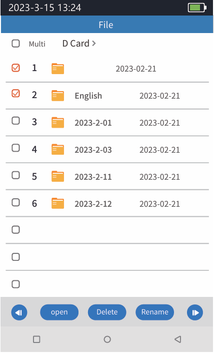
File Operation
File operation
All the test curves are saved in the TF card of the instrument. Press [file] to enter the file operation interface, and you can open and delete the file.
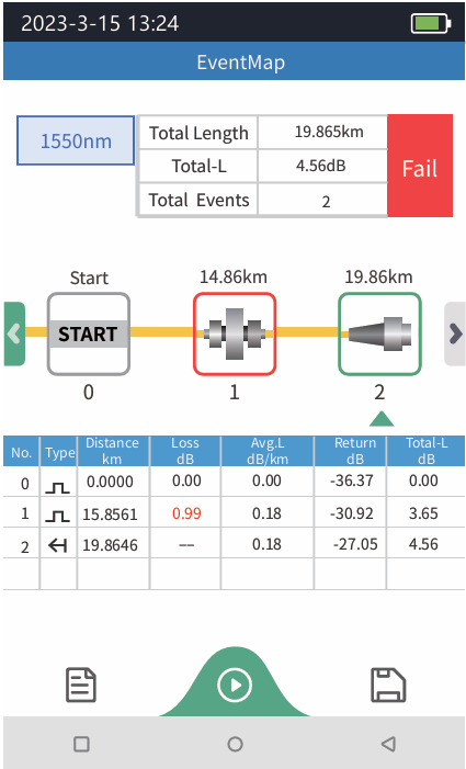
Event Map
The function is fully one key automatic test, and the information such as the length of the optical fiber link to be measured, the type of the joint and the position of the breakpoint are displayed graphically, and the results are clear and easy to understand.
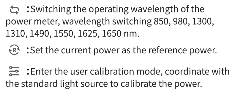
 OPM
It is used for signal power test and insertion loss test of various equipment and photoelectric components. It can identify and measure the power of 270/ 330/1k/2kHz frequency laser.
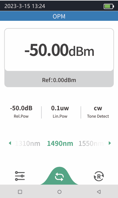
OPM
It is used for signal power test and insertion loss test of various equipment and photoelectric components. It can identify and measure the power of 270/ 330/1k/2kHz frequency laser.
The conversion relations of absolute power, relative power and linear power are as follows:
P_Abs.Pow = 10lgP_Lin.Pow/1mW
P_Rel.Pow = P_Abs.Pow - P_Ref.Pow
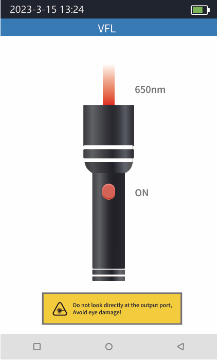
Inject the visible red light (650nm) into the optical fiber, and observe the light leakage position on the measured fiber, which can easily and accurately determine the position of the optical fiber fault point. It is applicable to the detection of the near end failure point of bare optical fiber, optical fiber jumper and other optical fiber and optical cable that can pool red light and the high loss section caused by micro bending.
- ON: Turn on the red light source and work continuously
- 1Hz: Red light source flashes once a second
- 2Hz: Red light source flashes twice in one second
- OFF: Turn off the red light source
Avoid looking directly at the laser output port, because the laser will cause damage to the human retina!
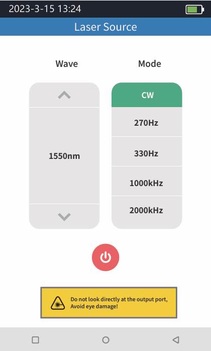
The output laser with the same wavelength as OTDR function, which can be used to test the parameters of telecommunication, CATV and LAN optical cables, test the insertion loss, isolation and return loss of optical passive components, and test the wavelength responsivity of detector.
There are five working modes: CW, 270Hz, 330Hz, 1kHz and 2kHz.

Avoid looking directly at the laser output port, because the laser will cause damage to the human retina!
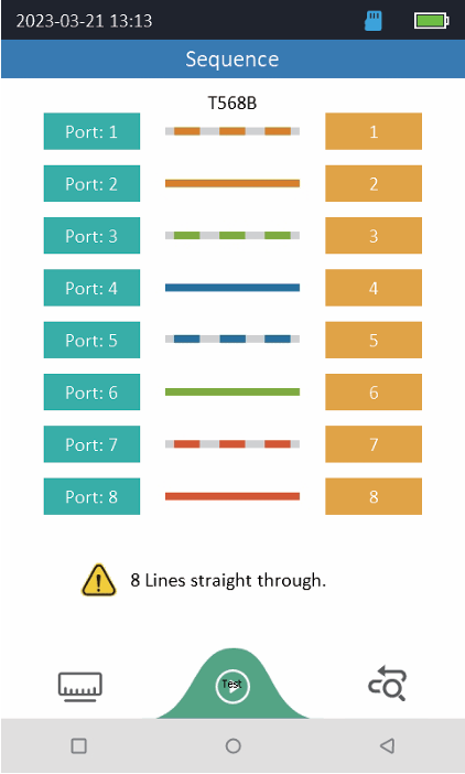
The RJ45 connector of a network cable can be a straight-through cable or a crossover cable. Through line is the cable both ends are T568A or both are T568B standard; The method of crossing lines is to use T568A standard at one end and T568B standard at the other end. After the RJ45 connector is made, you need to check network cables.
Step 1: Remove the distal end from the bottom of the instrument
Step 2: Connect the network cable under test between the instrument and the remote end
Step 3: Select the standard of network cable and click Start test
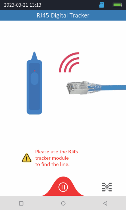
The function of network cable hunting is used to test the position and direction of the network cable, the signal sent by the transmitter is connected to the network line through the RJ45 interface, so that the induction signal is generated around the cable, and the signal is identified along the way and not at the end with the high sensitivity induction type line finder, so as to find the cable of this item.
Step 1: Remove the remote end (for Sequence use) and connect the network cable under test to the RJ45 interface of the instrument
Step 2: Click the hunt line, use an independent hunt to identify the network cable under test. The hunt line will make a drop sound and the red indicator light will blink, which is the network cable under test
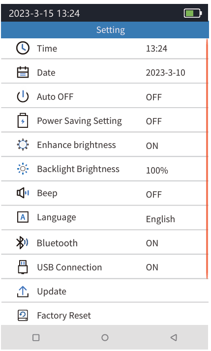
SET AUTOMATIC SHUTDOWN, BACKLIGHT BRIGHTNESS, TIME,LANGUAGE AND OTHER INFORMATION
- Time: Set the instrument time
- Date: Set the instrument date
- Auto OFF: 5/15/30/60 minutes/off
- Power saving Settings: 10/30/120/300/600s/off
- Enhance brightness: on/off
- Backlight brightness: 0/20/40/60/80/100%
- Beep: on/off
- Language: Set the native language type
- Bluetooth connection: on/off
- USB connection: Connect the computer through Type-C to make the device virtual as a U disk, and you can export the files inside the device
- Updates: Native software update
- Factory reset: Restore all default parameters in the system Settings
- About this mac: View the information and alarm records of the machine
- Operation instructions: Scan the code to view the operation video, common problems and solutions